I would like to modify a VGA Library for a Nucleo device

Good morning.
I;m programming on a ST Nucleo 746zg device, and I would really like to build a VGA signal just to test what would be like to have it on the board. I have read a couple of threads on mbed forum, but the only one suitable to me seems to be the one in New VGA 640x400 70Hz library | Mbed

which uses a library ( vga640x400graphic) that moves all the PWM signals (VSync and HSync) and the signal of the video.

My problem is that it uses the DIP5 , DIP8 and DIP25 pins, so initially I thought it would have been easy to check the prescalers, change the pins according to mine device and make it works to print a couple of line on a VGA screen. I could never found where these are set.

I believe that having a VGA interface on a Nucleo would really be great, so I’m open to every suggestion to do it.

Marco

If I understood you correctly, you are starting from a blank nucleo board and want to add a VGA?

Yeah, the problem is that the library is low-level and written for a different chip manufacturer (NXP and you are using STM, so I am afraid they really aren’t compatible.

So if you really want it you will have to write it on your own. Or, the good news is, that you don’t need to limit yourself to looking at Mbed forums, you can search for any STM32 project that uses VGA since for the most part, you can use standard HAL code alongside MBED.

However, if you start from a low level, I recommend watching this video. The dude made VGA driver from hardware chips, with almost no software. It will give you an overview of everything that is needed to make VGA work.

2 Likes

What an amazing video! Thanks for sharing! :slight_smile:

thank you, aoreskovic, for the reply.
I knew the video, it’s really a good start point. However to make it work it would be necessary to use the DMA to move the HSync and the video signal, and a PWM to move the VSync.

This seems difficult, so at least to do it someone should know really good how DMA works and needs some guide/tutorial on DMA.

I hoped that there would be some program that did something similar that could be used to do it.

I mean, using dma seems a topic for a really advanced user

@aoreskovic:
after thinking about your suggestion, reviewing the video a couple of times I thought that a part of it could be done with the PWM (on my board they are pretty fast); the code would be something like this:

#include “mbed.h”

// Signal is 800x600@60Hz
// DigitalOut myled(LED1);
Serial pc(USBTX, USBRX);
PwmOut Hsyncpwm(PA_7);
PwmOut Vsyncpwm(PA_8);
DigitalOut DIRE(D5);
Ticker pixel_scan;
int row = 0;
int column = 0;
double frames;
bool buffer [800][600];

int main() {
pc.baud(115200);
//fill the buffer
for (row = 0; row < 800; row++){
for (column = 0; row < 600; row++)
buffer[row][column] = 0;
}

pc.printf("Starting VGA trasmission\r\n");
Initialization();
while 1
 sleep 1;
 pc.print("printed %d frames;\n", frames);
 if (column == 0) 
    frames++;

}
//set the PWM and the ticker that moves pixel from buffer to exit
void Initialization() {
Hsyncpwm.pulsewidth_us(23.2);
Hsyncpwm.period_us(26.4);
Vsyncpwm.pulsewidth_ms(16.7);
Vsyncpwm.period_ms(16.57);
pixel_scan.attach_us (pixel_render, 0.25)
}

void pixel_render();{
DIRE = buffer [row][column];
if (row == 800)
column++ %600;
row++ %800;
}

may I have please your honest opinion on it?
Outputting a buffer like this would be already a success for my purpose

Marco

@MMastro

First, a bit of a tangent:

It might work since 746zg is very fast. Generally, you have here 3 levels of libraries. The lowest are ARM_LL (low level) that works on the registry level. To write code that you really need to look into datasheets and what registers do what. The fast lib for the example you linked in the original post was written this way.

on STM next level up are the HAL libraries - Hardware Abstraction Layer. Much simpler, but still powerful. The code uses LL in the background.

And then you have Mbed libraries, that use HAL in the background - even simpler, but slower, and less powerful. (I haven’t worked much with timers in Mbed, but an example is that STM supports level inversion on USART, Byte inversion, and some other features that are not supported in Mbed Serial).

What I see with the timers is, that generally on STM, not every pin is PWM capable. There is some select number of pins that are connected to the Timers, and those timers can output directly to the Pin.

What I think the Mbed does is have one timer, and use interrupts to toggle the digital out value of GPIO pins - this is slow. Using Timers the output is independent of Code execution, but using interrupts the code needs to halt every so often to change pin outputs.

But, Generally, for a 216 MHz device, you may be fine. If you want to dwell deeper here is a link General-purpose timer cookbook for STM32 microcontrollers.

Now, bask to this.

Few recommendations will help you debug.

Vsyncpwm.pulsewidth_ms(16.7);
Vsyncpwm.period_ms(16.57);
  • Your pulse width is larger than the period.
  • Keep in mind that you don’t need “just” the pwm, you need to create the high-level signals with precise low-level pulses, like this.
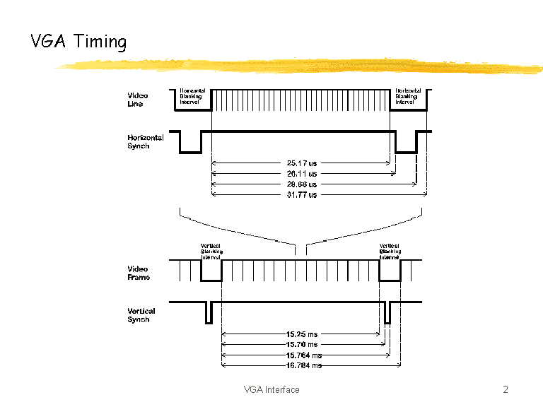

And the zero position is important.

I would follow the bring up procedure from the video:

  1. Start without pixel drawing - just output the Hsync and Vsync and see if the monitor recognizes the resolution. One of the potential problems I see is that your Hsync and Vsync aren’t, well synced.
    at the begging of the frame, they start both at zero, but one Vertical period is equal to 627.6515 Horizontal periods. that means that the first frame will start OK, at the beginning of the next one the Hline won’t be at zero, but at 0.6515 of the period - you need to sync them up at the beginning/end of the frame.
  2. Maybe start with a lower resolution first? just as a sanity check.
  3. Then start first changing the colors of the full-frame, each frame, then change the color of the lines and then change pixels.

Hello,

I have never tried it but this demo program could help too.

Best regards, Zoltan

@ aoreskovic:
I learned what you was saying the hard way: I connected the Nucleo to the tv and the output is
"++ MbedOS Fault Handler ++

FaultType: HardFault

Context:
R0 : 080051B1
R1 : 20050008
R2 : 00000001
R3 : 2000052C
R4 : 00001168
R5 : 00000000
R6 : 0800EE24
R7 : 000000C8
R8 : 2000CB1C
R9 : 00000000
R10 : 00000000
R11 : 00000000
R12 : 2000CB1C
SP : 2004FFC0
LR : 2000D72C
PC : 080051E0
xPSR : 21000042
PSP : 20005438
MSP : 2004FFA0
CPUID: 410FC271
HFSR : 40000000
MMFSR: 00000000
BFSR : 00000082
UFSR : 00000000
DFSR : 00000009
AFSR : 00000000
BFAR : 20050009
Mode : Handler
Priv : Privileged
Stack: MSP

– MbedOS Fault Handler –

++ MbedOS Error Info ++
Error Status: 0x80FF013D Code: 317 Module: 255
Error Message: Fault exception
Location: 0x8008FDF
Error Value: 0x80051E0
Current Thread: main Id: 0x2000CF24 Entry: 0x800936F StackSize: 0x1000 StackMem: 0x200044C0 SP: 0x2004FF44
For more info, visit: mbedos-error
– MbedOS Error Info –

= System will be rebooted due to a fatal error =
= Reboot count(=5) reached maximum, system will halt after rebooting ."
So this error I did with timing doesn’t make it work. I’m modifing the program because according to the program the Nucleo RAM is not enough for this resolution (I was reaaally optimistic). The PIN I used are all PWM capable.

@ hudakz: yes this program is great, however I can;t compile it as it says “Error: Fatal error: A1023E: File “…/…/build/STM32F3-Discovery-minimal/src/TOOLCHAIN_ARM_STD/startup_stm32f303xc.NUCLEO_F746ZG.E” could not be opened: No such file or directory
1 Error, 0 Warnings”

So I believe the library is only for the discovery.
Thank you for your help so far. I need to figure out how to sincronize the signal at the beginning of the frame

All right, sorry for the long pause, I tried again the program:
No television of mine can recognize the vga once connected. However I tried with my frequencimeter, VSinc signal is working, the HSync seems to be too fast for it (my limit is 20MHz).

Also I still do not have any idea on how to reset the HSync signal when a new frame should appear.

All right, there is no way to make my program work, I tested it. I made a different program, which output a Composite signal, but it doesn’t get recognized either.

the program is

#include “mbed.h”
#include “buffer.h”

Serial pc(USBTX, USBRX);
AnalogOut aout(PA_5);
int row = 0;
int column = 0;
double frames;
int grade;
Thread thread;
Timer t;

//pixels of Composite signal
void picture (){
for (row = 0; row < 767; row++){
aout = Image1[row][column]grade 0.1f;
wait_ns(68); // pixel duration, total line =52ms
}
pc.printf(“\n @@@@@@@%d \n”, column);
}

//Sync signal
void sync (){
t.start();
aout = 0.1f;
wait_ns(1500); //front porch
aout = 0.0f;
ThisThread::sleep_for (4);
wait_ns(700); // sync line 4700ns
aout = 0.1f;
ThisThread::sleep_for (5);
wait_ns(800); // back porc 5800ns
if (column == 0) {
frames++;
}
picture();
if (row == 767)
column++ %575;
if (column == 576)
column = 0;
sync ();
}

int main() {
pc.baud(115200);
pc.printf(“Starting trasmission…\n”);
thread.start(sync);
while (1) {
ThisThread::sleep_for(1000);
pc.printf(“\nprinted %lf frames;\n”, frames);
grade++ %3;
}

}

In detail I measured that the initial part until backproch works, it takes 11.5 ms that should be correct. I checked and all the pixels in the picture() routine gets loaded. I measured the output Voltage, and it doesn’t go neither under 0 nor over 1V that should be correct (the signal is obviously fast)