
Hi everyone,
does anyone know how to select LSE crystal as clock source on stm32f103rb? I know I have to set RTCSEL bits in RCC_BDCR register to 01 but I have no idea how to do this using the mbed online compiler.
I really appreciate if anyone could help me.
Thank you very much for your help.
Chiara
Hello Chiara,
You can use a mbed_app.json configuration file with the following content:
{
    "target_overrides": {
        "*": {
            "target.lse_available": 1
        }
    }
}
Best regards, Zoltan
Hello Zoltan!
Where can I get a description of all mbed_app.json parameters?
Hello Nik,
I have no simple answer to your question. You can find the related information here.
Mbed suggests to examine the available configuration parameters by using mbed-cli command:
mbed compile --config
or
mbed compile --config -v
But I’m afraid that it doesn’t list all of them.
Best regards, Zoltan
Thanks for that too! ![]()
Thank you very much for the reply! Where can I find this configuration file or where should I add it?
Best regards,
Chiara
Hello Chiara,
If there is no mbed_app.json file in your project yet then add one:
- Right-click on the project name and select
New File ... - Type
mbed_app.jsoninto theFile Nameedit box and save it. - Open the
mbed_app.jsonfile for editing andCopy&Pastethe content I provided to the file.
Best regards, Zoltan
1 Like
Thank you! As you suggested I created a new file but I didn’t see any improvement in my PCB. The delay is still very big which means to me that another internal oscillator is used instead of the LSE. Any idea how to solve this?
Regrads,
Chiara
Hello Chiara,
Could you please show us your program code and explain which delay do you mean?
- Copy&paste the code to your response.
- Prepend and append with three back-tick characters (```) on a separate line. Like:
```
source code
of your program
```
Best regards, Zoltan
Here is the code. It is very simple. It just takes data from 7 analog inputs, an IMU and a nRF24L01 transceiver and sends them via bluetooth. Data are sent every 200 ms using ticker.attach() function and, in my opinion, this is where the delay is introduced due to the inaccuracy of the internal clock.
Thank you very much for the attention and the help.
Best regards,
Chiara
#include "mbed.h"
#include "nRF24L01P.h"
#include "LSM9DS1.h"
#include <Ticker.h>

#define STIME 0.020  // sampling rate 50 Hz

Ticker sampl; // interrupt

// 7 analog inputs from the insole
AnalogIn sig1(PA_0);
AnalogIn sig2(PA_1);
AnalogIn sig3(PA_4);
AnalogIn sig4(PB_0);
AnalogIn sig5(PC_1);
AnalogIn sig6(PC_0);
AnalogIn sig7(PC_2);

DigitalOut o1(PA_12);

DigitalOut myled(LED1);
nRF24L01P ant(PB_15, PB_14, PB_13, PB_12, PC_6, PC_7); // antenna connection (mosi, miso, sck, csn, ce, irq)
LSM9DS1 imu(PB_9, PB_8, 0xD4, 0x38); // IMU connection (PB_9 = SCL_IMU, PB=8 = SDA_IMU, 0xD4 = xgAddr, 0x38 = mAddr)
Serial bt(PA_9, PA_10);  // bluetooth connection (PA9 = RX_BT, PA_10 = TX_BT)

bool samplingTime = false;
bool not_fast_enough = false;

unsigned short val[7];

char data[18];

// send 16 bits divided into 2 bytes via bluetooth
void send16(unsigned short value)
{
    bt.putc(value & 0xFF);
    bt.putc((value >> 8) & 0xFF);
}

// check if all data has been send
void samplInt()
{
    if (samplingTime == true) {
        not_fast_enough = true;
    }
    samplingTime = true;
}

// sample and send the data from the insole and from the IMU
void SampleAndSend()
{
    if(not_fast_enough){
	not _fast_enough = false;

        send16(short(99));
        send16(short(99));
        send16(short(99));
        send16(short(99));
        send16(short(99));
        send16(short(99));
        send16(short(99));

        send16(short(99));
        send16(short(99));
        send16(short(99));

        send16(short(99));
        send16(short(99));
        send16(short(99));
    }
    else{
        val[0] = sig1.read_u16();
        val[1] = sig2.read_u16();
        val[2] = sig3.read_u16();
        val[3] = sig4.read_u16();
        val[4] = sig5.read_u16();
        val[5] = sig6.read_u16();
        val[6] = sig7.read_u16();

        for (int i = 0; i < 7; i++) {
            send16(val[i]>>4);
        }

        imu.readAccel();
        imu.readGyro();

        send16(imu.gx);
        send16(imu.gy);
        send16(imu.gz);

        send16(imu.ax);
        send16(imu.ay);
        send16(imu.az);
    }

    ant.read(NRF24L01P_PIPE_P0,data,sizeof(data));
    for (int j=0; j<18; j++){
         bt.putc(data[j]);
    }
}

void inter() {

    while(bt.getc() != 'E'){};
    sampl.attach(&samplInt, STIME);
}

main(void) {

    o1 = 0;

    bt.baud(115200);

    imu.begin();

    ant.powerUp();
    ant.setRfFrequency(2500);
    ant.setRfOutputPower(0);
    ant.setAirDataRate(250);
    ant.setTransferSize(18, NRF24L01P_PIPE_P0);
    ant.setReceiveMode();
    ant.disableAutoAcknowledge();
    ant.disableAutoRetransmit();
    ant.enable();

    bt.attach(&inter, Serial::RxIrq);

    while(1) {
        if (samplingTime == true) {
            SampleAndSend();
            samplingTime = false;
        }
    }
}
Hello Chiara,
STM32F103RB clock configuration
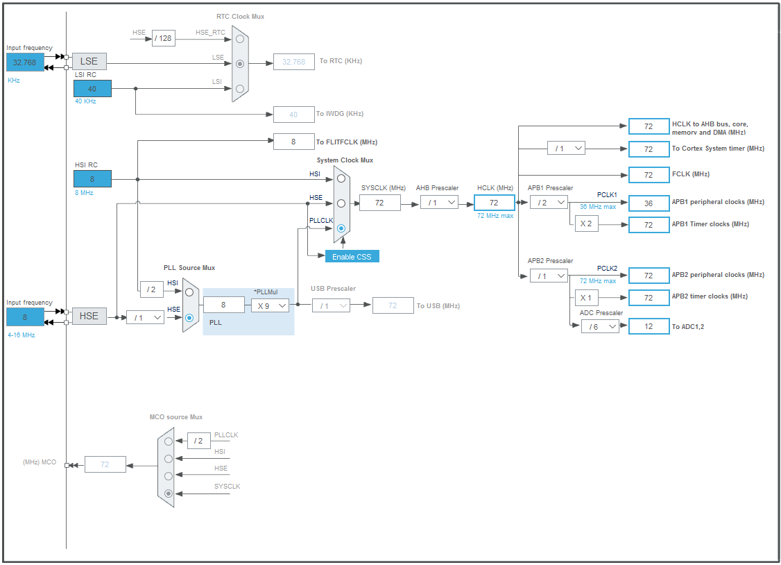
As you can see in the picture above the LSE (Low Speed External) input is used only to clock the Real Time Clock (RTC) (which is not used in your program). All the other components (including the processor) can be clocked either from a High Speed Internal RC oscillator (HSI RC), which is less accurate, or from a High Speed External clock source (HSE). The High Speed External clock source could be either High Speed External clock signal (default for NUCLEO-F103RB) or a High Speed Oscillator using an External Crystal.
If you’d like to use an external crystal put the following into the mbed_app.json file:
{
    "config": {
       "clock_source": {
           "value": "USE_PLL_HSE_XTAL"
        }
    }
}
Please note that the NUCLEO-F103RE board doesn’t have an onboard crystal (neither LSE nor HSE). You have to add one (along with decoupling capacitors) by yourself.
But I don’t think that will solve your problem. To defer execution of time consuming operations you can try to use EventQueue rather than a Ticker.
Best regards, Zoltan
Dear Zoltan,
Thank you vero much, I really appreciate your help. I’ll try doing what you suggested immediately. I just have one more question… what clock source is ticker driven by? Is it an internal clock of the MCU? What is its accuracy?
Thank you very much for your help.
Best regards,
Chiara
Hello Chiara,
The related Mbed documentation says:
RTOS Ticker
Platforms using RTOS, including Mbed OS, need a mechanism for counting the time and scheduling tasks. A timer that generates periodic interrupts and is called system tick timer usually does this. Under Mbed OS, we call this mechanism the RTOS ticker.
SysTick is a standard timer available on most Cortex-M cores. Its main purpose is to raise an interrupt with set frequency (usually 1ms). In addition, many Mbed OS platforms implement timers as part of peripherals. Mbed OS supports using SysTick or the peripheral timers as RTOS ticker.
The Mbed OS platforms uses SysTick as the default RTOS ticker, but if you want to use one of the peripheral timers as your RTOS ticker, you can override the default SysTick timer. For example, see Low Power Ticker on how to use an external low power timer to perform power efficient timing operations that only require millisecond accuracy.
Because they both use HSE for clocking I think in regard with accuracy it doesn’t matter whether the RTOS ticker is clocked by SysTick or a peripheral timer. Since one can call the attach_us member function to schedule recurring interrupts a Ticker should have microsecond accuracy.
Best regards, Zoltan