right I am (trying to) set up CAN for my first time. I am not exactly using mbed by I figures I could get help here.
I am programming an STM32F429 on an Nucleo F429ZI using the STM32CubeIDE. I want to program it using the CMSIS.
I am pretty confident that I have programmed it (mostly of course) correct.
It is something but I am pretty sure that this is not an CAN message.
The Logic analyser is connected to the TX Pin on the nucleo board.
When I change the bit timing, the output changes slightly, and when I change the content of the CAN massage, e.g. the data, nothing happens.
Does anyone have an idea would I might have messed up, or know where I could get help?
Although the STM32F429 microcontroller is equipped with a CAN bus controller an additional external CAN transceiver (like the MCP2551 or TJA1040, or etc.) is needed to connect it to a CAN bus. For example as shown here. However, for short distances at lower CAN speed you can try this solution.
I have a CAN transceiver here (an ADM3053), sadly just one, but at first I just wanted to configure one board to see if I´m doing it correctly and than the second.
It is good to know that it can work without Transceiver, because I don´t have a second.
To make something clear: what is the output of an CAN_TX Pin? As far as I´m concerned it should be the normal CAN standard, or am I wrong? So I should see the message in the Logic Analyser, because in order to knoe that the CAN bus only has one Node, which is insufficient, it has to send the message, can´t I see this?
If it helps, or if it helps me: I´ve got an CAN Analyser.
On this chart you can see both the “driver logic” (CAN_TX Pin signal) and also the differential voltage signal on the CAN bus generated by the CAN transceiver.
because in order to knoe that the CAN bus only has one Node, which is insufficient, it has to send the message, can´t I see this?
Normally, when there is only one node connected to a CAN bus it will fail after several trials to connect. However, in such case you can put the node into a loop-back mode so it will connect to itself and you should be able so see that.
Thank you very much, that is the chart I was looking for!
Thats what I thought, but since I don´t see anything (screenshot from Logic Analyser) there must be another mistake I made.
I will try this further, I tested it a few times but I haven´t received anything, it could be because I made a mistake configuring the filters or because there is another mistake (which is more likely to me). When using the loop-back mode, do I have to connect the TX and RX Pin or does this happen internaly?
In loop-back mode the controller does not send messages over the line, it handles sending and receiving the messages internally. So you don’t have to connect the node to the CAN bus physically. However, this implies that the loop-back mode is suitable to test the software but not the hardware.
But that is a good thing for my because there has to be a Software error, I´m relatively confident that the hardware is (mostly) working (if it were complete).
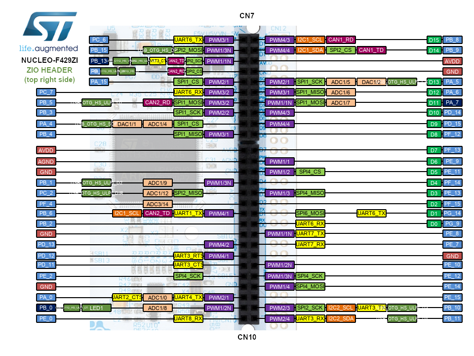
Actually, the STM32F429ZI is equipped with two CAN controllers. CAN1 is available at PB_8, PB_9 pins and CAN2 at PB_5, PB_6 pins. So you can test also the hardware after connecting these two controllers to the same CAN bus as shown here and here. If you have only one CAN transceiver available then you can try to connect them using the diodes as explained in the Siemens application note AP2921.
I´m a little bit confused, where do you got this documentation from?
I in the documentation I found the Pins PD_0 and PD_1 are the pins which the CAN controller uses.
You are completly right, but I suppose that there is two sets of pins per CAN controller because in the same data sheet you can see that PD_0 and PD_1 are also pins of CAN 1.
Anyways there is a reason why I think I should use PD_0 and PD_1, maybe it is unnacessary or there is a reason but on the board it is written at PD_0 and PD_1 that they are used for CAN:
You can select any of the pins mapped to the CAN controllers and pass them to the CAN constructor to create a CAN object (and properly configure the selected CAN controller). However, make sure they are connected to the same controller and not used at the same time for other alternate function (like USB or RMII). For example, any of the following options should work:
That should be correct by now but I kinda found the error now. The CAN message never gets send and I get an transmission error.
Also I realized that multiple bits in the error status register are set, e.g. BOFF, EPVF, EWGF


